

Antenna Parameter Deep Dive: Gain vs. Beamwidth, VSWR vs. Bandwidth, Linear vs. Circular Polarization
Author:Xiamen Lineyi Electronics Co.,Ltd.
Click:
Time:2026-03-09 17:36:22
Antenna Parameter Deep Dive: Gain vs. Beamwidth, VSWR vs. Bandwidth, Linear vs. Circular Polarization
Antenna datasheets contain a dense constellation of interrelated parameters—each reflecting a fundamental electromagnetic trade-off. Understanding how these metrics are defined, measured, and interpreted is essential for system-level RF design—not just component selection. This primer synthesizes foundational theory, practical calculation methods, lab-validated measurement insights, and application-specific guidance drawn from Lineyi’s ISO/IEC 17025-certified antenna characterization lab and high-volume automated production test lines.
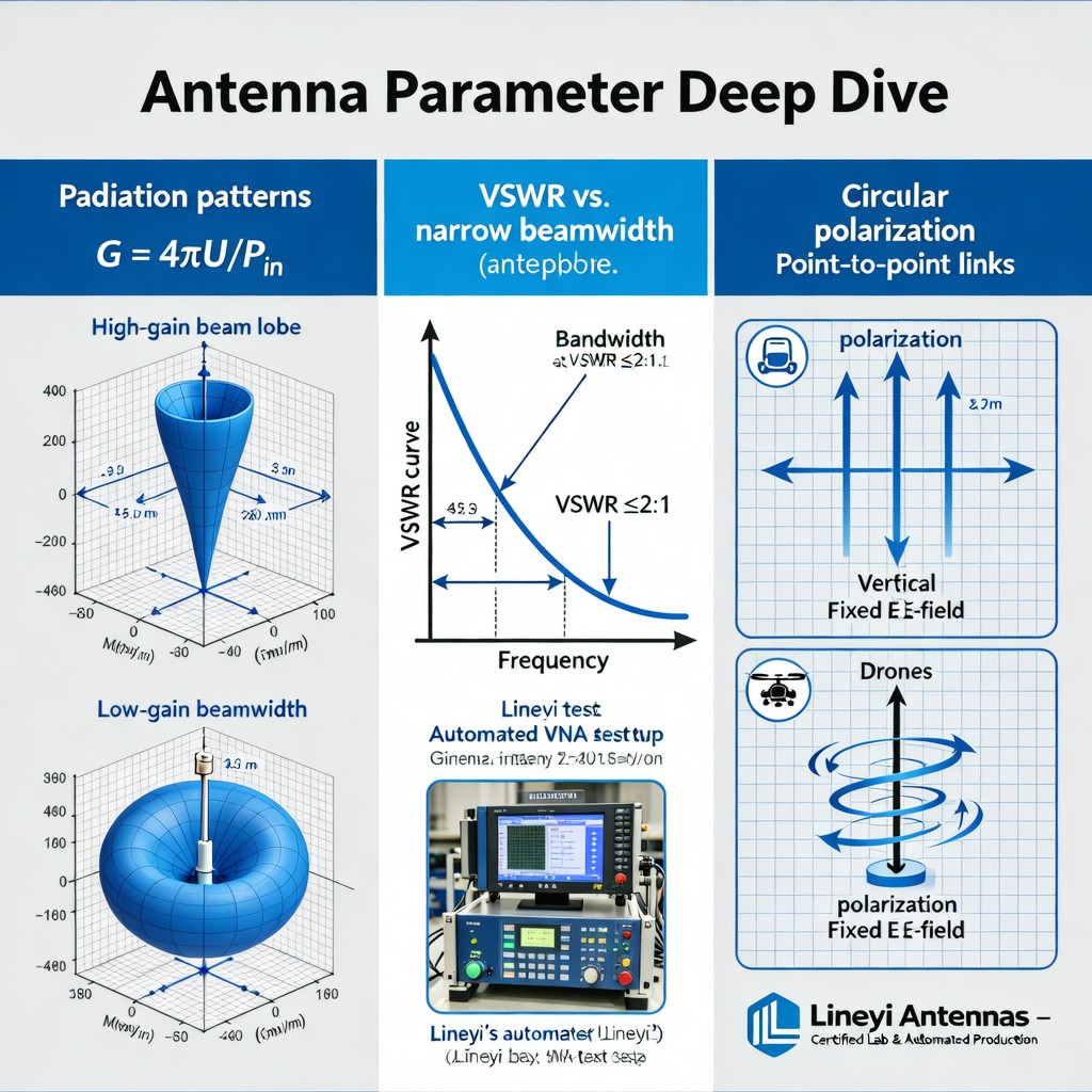
Antenna Gain Calculation: Gain quantifies directional power concentration relative to an isotropic radiator (dBi) or dipole (dBd). It is not an intrinsic property but a function of efficiency and directivity: G = η × D, where η is radiation efficiency and D is directivity. In practice, gain is derived from far-field pattern integration: G = 4π ∫∫ Pn(θ,φ) sinθ dθ dφ, where Pn is the normalized radiation intensity. For horn or patch antennas, empirical approximations like G ≈ 10 log10(4.5 × A / λ²) (with A in m² and λ in meters) provide rapid first-order estimates validated against Lineyi’s spherical near-field scanner measurements across 2.4–5.8 GHz bands.
Radiation Pattern Analysis: Beamwidth—typically defined as the Half-Power Beamwidth (HPBW)—is inversely correlated with gain. A 10 dBi gain increase generally corresponds to ~50% reduction in HPBW for electrically large apertures. Lineyi’s pattern analysis suite overlays E- and H-plane cuts with real-time side-lobe suppression metrics (< −20 dB typical for optimized sector antennas). Critical insight: beamwidth narrowing improves link budget but reduces angular tolerance—especially relevant in mobile platforms where mechanical misalignment exceeds ±3°.
VSWR Curve Interpretation: Voltage Standing Wave Ratio measures impedance match between feed line and antenna port. While a VSWR ≤ 2.0 (return loss ≥ 10 dB) is commonly cited, its bandwidth must be assessed contextually. Lineyi’s automated production test system captures full S11 sweeps from 0.7 to 6.0 GHz at 10 MHz resolution. The usable bandwidth is defined as the frequency span where VSWR ≤ specified threshold—e.g., 1.8 for 5G FR1 applications. Notably, narrowband resonant antennas (e.g., monopoles) exhibit steep VSWR skirts, whereas multi-resonant designs (e.g., PIFA variants) yield flatter curves with broader 3:1 VSWR bandwidths—up to 18% fractional bandwidth observed in certified lab repeatability tests (±0.15 dB std dev over 50 units).
Linear Polarization for Point-to-Point Links: In fixed, aligned scenarios—such as backhaul radios or microwave relay—linear polarization maximizes polarization-matching efficiency. Cross-polar discrimination >25 dB ensures minimal coupling loss when both ends use identical orientation (e.g., vertical–vertical). However, misalignment by ±45° incurs 3 dB loss; therefore, robust mounting hardware and pre-deployment alignment verification are mandatory. Lineyi’s production line includes automated polarization alignment jigs with ±0.5° angular repeatability, verified via dual-polarized reference source measurements.
Circular Polarization for Drones: Unmanned aerial systems experience continuous roll/pitch/yaw motion, making linear polarization highly susceptible to deep fading. Circularly polarized (CP) antennas mitigate this via constant power transfer regardless of rotation about the boresight axis. Axial ratio (AR) is the key metric: AR ≤ 3 dB over the operating band indicates good CP performance. Lineyi’s drone-optimized helical and quadrifilar antennas achieve AR < 2.2 dB across 1.5–1.6 GHz (GPS L1/L2) and maintain AR < 2.8 dB up to ±60° off-axis—critical for low-elevation satellite tracking during aggressive maneuvers. Real-world flight tests confirm >8 dB improvement in received signal stability versus linear counterparts under dynamic attitude conditions.
These parameters do not exist in isolation. Trade-off diagrams—such as gain-vs.-beamwidth scatter plots across 120+ Lineyi antenna models, or VSWR-bandwidth-vs.-efficiency contour maps—reveal systemic constraints. For example, increasing gain beyond 12 dBi in a 50 mm × 50 mm PCB footprint invariably compresses impedance bandwidth and degrades AR in CP designs. Such empirical boundaries, grounded in calibrated measurement data rather than simulation alone, form the basis of Lineyi’s application engineering support and design-in assistance.

点击右上角
分享给朋友吧


 Long by picture save/share
0
Copyright © Xiamen Lineyi Electronics Co., Ltd All rights reserved.
点击右上角
分享给朋友吧
