

From Theory to Deployment: Microwave Antenna Sizing, Mounting & Environmental Readiness
Author:Xiamen Lineyi Electronics Co.,Ltd.
Click:
Time:2026-03-13 18:51:05
Microwave Antenna Installation Guide: Bridging Engineering Theory and Field Deployment
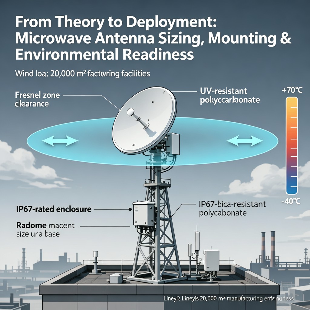
Deploying microwave antennas is far more than selecting a model based on frequency band or gain specifications. Real-world reliability hinges on how precisely theoretical design principles translate into physical installation decisions — especially under variable environmental stressors. This guide distills field-proven practices from Lineyi’s integrated 20,000 m² manufacturing and validation ecosystem, where every antenna undergoes rigorous environmental simulation before shipment.
Mounting Height & Fresnel Zone Clearance: The Invisible Performance Boundary
Mounting height directly governs path clearance — not only line-of-sight but, critically, the first Fresnel zone. For microwave links operating above 2 GHz, obstruction of more than 20% of the first Fresnel radius can induce significant signal diffraction loss and multipath fading. At 6 GHz over a 5 km path, the 60% Fresnel radius exceeds 4.2 m — meaning even mature tree canopies or low-rise structures may degrade link margin if mounting height is underspecified. Lineyi recommends calculating clearance using ITU-R P.530-17 methodology and validating with site-specific terrain modeling tools prior to pole or tower installation.
IP67 Antenna Enclosures: Beyond Dust and Water Resistance
An IP67 rating signifies full dust ingress protection and immersion resistance up to 1 m for 30 minutes — essential for coastal, desert, and heavy-rainfall deployments. However, true environmental readiness demands more than compliance testing: it requires gasket aging validation (per ISO 11600), UV-stabilized polycarbonate housings, and thermal-cycle-tested cable glands. All Lineyi IP67-rated antennas feature dual-lip silicone gaskets with compression-set retention after 2,000 thermal cycles (−40°C to +85°C), ensuring long-term sealing integrity across seasonal extremes.
Antenna Wind Load Rating: Structural Integrity Meets Aerodynamic Design
Wind load is not merely a mechanical spec — it determines mast selection, bracket reinforcement, and allowable array stacking. Lineyi’s wind tunnel–validated antenna models report both projected area and drag coefficient (Cd) — enabling precise calculation per EN 1991-1-4. For example, a 0.6 m parabolic antenna with Cd = 1.1 generates ~1,380 N force at 150 km/h (41.7 m/s). Our standard mounting kits are rated for 220 km/h gusts, incorporating finite-element–verified U-bolt clamping geometry and non-slip anodized aluminum interfaces that eliminate micro-movement-induced fatigue.
Outdoor Antenna Temperature Range: Thermal Resilience Across Climates
Operational temperature range must account for both ambient extremes and solar loading. While many datasheets cite −40°C to +65°C, real-world surface temperatures on black radomes in direct sunlight can exceed +85°C — risking dielectric constant drift in feed components and connector torque relaxation. Lineyi’s outdoor antennas are qualified across −40°C to +85°C continuous operation, with accelerated life testing including 1,000 hours at +85°C/85% RH and thermal shock cycling from −55°C to +125°C. All RF connectors use silver-plated beryllium copper with cold-welded interface geometry to maintain VSWR stability under thermal expansion mismatch.
Antenna Radome Material: Dielectric Consistency and Mechanical Durability
Radome material selection balances RF transparency, impact resistance, UV stability, and thermal expansion compatibility with the reflector. Lineyi utilizes custom-formulated fiberglass-reinforced polyamide (PA66-GF30) for high-gain parabolic units — offering a stable dielectric constant (εr = 3.2 ±0.05) from −40°C to +85°C, tensile strength >180 MPa, and zero yellowing after 5,000 hours UV exposure (per ASTM G154). For compact sector antennas, we employ UV-stabilized polycarbonate with anti-static coating to prevent dust adhesion and ensure consistent beam pattern fidelity over 15+ years of service life.
Microwave antenna deployment success lies at the intersection of electromagnetic theory, mechanical engineering, and environmental science. By grounding each specification — from IP67 sealing architecture to wind-load–optimized mounting kinematics — in production-scale validation, Lineyi ensures that what ships from our facility performs predictably in the field, year after year. Whether deploying in sub-zero tundra or tropical monsoon zones, engineers can rely on rigorously tested, application-ready hardware backed by empirical data — not just datasheet promises.

点击右上角
分享给朋友吧


 Long by picture save/share
0
Copyright © Xiamen Lineyi Electronics Co., Ltd All rights reserved.
点击右上角
分享给朋友吧
