

The Core Components of an Optimized RF Front-End
Author:Xiamen Lineyi Electronics Co.,Ltd.
Click:
Time:2026-01-21 17:22:39
In high-performance wireless systems, the journey of a radio frequency (RF) signal from the antenna to the digital processor is fraught with potential degradation. Superior rf antenna system integration is not merely about connecting components; it's about architecting a cohesive front-end where the antenna, passive networks, and active semiconductors work as a unified system. The critical first few stages—encompassing the antenna and rf circuit, the impedance matching network, and the low noise amplifier lna—determine the ultimate sensitivity, selectivity, and linearity of the entire receiver. Neglecting this integration is akin to using a high-resolution telescope with a dirty, misaligned lens.
This article delves into the core hardware blocks of an optimized RF front-end, explaining their individual functions and, more importantly, their critical interdependence in determining overall rf system performance.
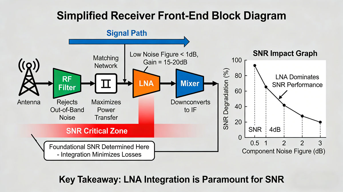 A simplified receiver front-end block diagram. The signal chain from antenna to LNA is where the foundational signal-to-noise ratio (SNR) is largely determined, making integration here paramount.
The Starting Point: The Antenna as a Source
The antenna is the system’s transducer, converting electromagnetic waves into electrical signals. However, from a circuit perspective, it is not a perfect source. It presents a complex impedance (Z_antenna = R + jX) that varies with frequency and environment. A core tenet of effective rf antenna system integration is acknowledging this impedance and designing the subsequent circuitry to accept it optimally. The goal is to extract maximum signal power, which only occurs when the source and load impedances are conjugate matched.
The Critical Bridge: The Impedance Matching Network
This is where theory meets practice. An impedance matching network is a passive circuit (typically using inductors (L), capacitors (C), and sometimes transmission lines) placed between the antenna and the first active component (the LNA).
- Primary Function: To transform the complex impedance of the antenna to the optimal input impedance of the LNA (almost universally 50 ohms for system modularity and minimum reflection).
- Why it's Non-Negotiable: Without matching, a significant portion of the precious received signal power is reflected back toward the antenna (quantified by high VSWR), never reaching the amplifier. This directly reduces sensitivity. Furthermore, it can destabilize the LNA, causing oscillations or degraded noise figure.
- Design Considerations: Matching networks can be narrowband (for a specific frequency) or broadband. They must be designed with high-quality, low-loss components (high-Q inductors, stable capacitors) to avoid dissipating the signal power as heat before it’s even amplified.
 The Smith Chart is an essential tool for designing impedance matching networks, visualizing the transformation of complex impedance to the desired 50-ohm point.*
The First Active Stage: The Low-Noise Amplifier (LNA)
The low noise amplifier lna is the guardian of signal integrity. Its role is to amplify the vanishingly weak signal from the antenna (often measured in microvolts) without significantly adding electronic noise of its own.
- The Key Metric: Noise Figure (NF). Measured in decibels (dB), the Noise Figure quantifies how much the LNA degrades the signal-to-noise ratio (SNR). A lower NF (e.g., 0.5 dB vs. 3 dB) means a much better ability to hear weak signals amidst the inherent noise floor, directly enhancing receiver range and sensitivity.
- The Delicate Balance: LNA design is a tightrope walk between low noise, high gain, good linearity (to handle strong signals without distortion), and input/output matching. Achieving the lowest possible noise figure often requires the LNA to “see” a specific optimal source impedance (Γ_opt), which may not be 50 ohms. This is where the impedance matching network plays a sophisticated role: it may be designed not for perfect 50-ohm match, but to present Γ_opt to the LNA transistor for absolute best noise performance—a technique called noise matching.
- Integration Context: The LNA must be placed as physically close as possible to the antenna feed point. Any trace length between them acts as a lossy element, degrading the noise figure before amplification can even occur. This is a key practical aspect of antenna and rf circuit layout.
The Unsung Hero: The Band-Pass Filter (BPF)
Often placed between the antenna and LNA (a preselector filter) or directly after the LNA, the band-pass filter is vital for rf system performance. It rejects out-of-band interference (e.g., from nearby radio transmitters, cellular bands) that could overload or desensitize the sensitive LNA. A well-integrated filter ensures the LNA only amplifies the signals of interest.
The synergy between these components defines a successful front-end. The antenna and rf circuit must be co-designed, with the impedance matching network serving as the tailored interface that allows the low noise amplifier lna to perform at its theoretical best. In the next article, we will explore the system-level challenges, measurement techniques, and advanced co-design methodologies that take this foundational integration to a higher level.
Achieving optimal rf antenna system integration requires components designed to work in harmony. Xiamen Lineyi's expertise in antenna design complements advanced RF circuitry. [Contact us] to explore how our antenna solutions can be tailored to match your specific LNA and filter requirements for superior front-end performance.

点击右上角
分享给朋友吧







 Long by picture save/share
0
Copyright © Xiamen Lineyi Electronics Co., Ltd All rights reserved.
点击右上角
分享给朋友吧
