

Research on Selection and Optimization Methods of Microwave Communication Antenna
Author:Xiamen Lineyi Electronics Co.,Ltd.
Click:
Time:2020-08-07 15:54:34
1 Introduction
With the rapid development of wireless communication technology, the application range of microwave communication technology communication is very wide. Microwave antennas are the most important part of microwave communication systems. Almost all information that can be transmitted by electromagnetic waves depends on microwave antennas for transmission and exchange. At the same time, microwave antennas can also radiate electromagnetic waves and other energy. Microwave antennas are the entrance and exit of the transceiver equipment of the microwave communication system, and the performance of the antenna directly affects the operation of the entire system. Although there are many research results on the optimization of microwave antennas, most of them are considered from a single factor, and the optimization effect is not very ideal. This article considers multiple factors and optimizes the selection parameters of microwave antennas to find a more reasonable selection method.
2 Research on factors to be considered when selecting microwave antennas
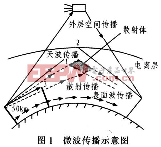
Figure 1 is a schematic diagram of microwave propagation. During transmission, microwave signals will be affected by the refraction and diffraction of the atmosphere, sea, ground, tall buildings, and mountain peaks, resulting in signal fading, distortion, and even interruption. Therefore, to optimize the microwave transmission antenna, it is necessary to study the influencing factors of microwave in the transmission process according to the basic characteristics of microwave communication, and then optimize to reduce signal fading and distortion.
2.1 Ground terrain factors
In the microwave communication system, signal transmission mainly uses the line-of-sight propagation of microwave. The frequency of microwave communication is mostly in the range of 2 to 20 GHz, and different terrain conditions have different reflection coefficients and level losses. When radio waves are transmitted in free space, the energy per unit area will be reduced due to free diffusion. The reduced energy is called free space transmission loss, which is expressed by Ls and the unit is decibel (dB). The calculation formula is:

In the formula, f is the transmitting frequency, GHz; d is the station distance, km.
It can be seen from equation (1) that forests, buildings, hills or ground obstacles will block part of the electromagnetic waves during the propagation of microwaves and increase the loss. The smooth ground or water surface can reflect part of the signal to the receiving antenna, and the vector addition of the reflected wave and the direct wave may cancel each other out and cause additional loss. Ground reflection has an important impact on line-of-sight propagation, and it is one of the main causes of level fading. However, when there is a blade-shaped obstacle (or mountain) blocking the microwave transmission path, if the peak of the obstacle happens to fall on the connection between the receiving antenna and the transmitting antenna of two adjacent microwave stations, the microwave transmission will increase by 6 dB level attenuation; when the spikes of obstacles exceed the connection, the level attenuation will increase faster. This situation should be avoided in practical applications. The transmission characteristics can be changed by changing the microwave transmission line or increasing the antenna. In order to better analyze the propagation characteristics of microwaves, the concept of Fresnel zone is applied for analysis. The radio waves from the wave source to the observation point can be considered to propagate through many Fresnel zones, and the combined field strength at the observation point E≈ E1/2 (E1 is the field strength of the first Fresnel zone), that is, as long as half of the first Fresnel zone is not blocked by the terrain. The field strength when propagating in free space can be approximated. To know how high the barrier is to meet the propagation conditions, the radius F1 of the first Fresnel zone must be calculated in m. The calculation method is:
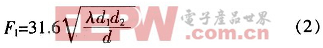
In the formula, d refers to the distance between sending and receiving, km; λ is the wavelength, m.
It can be seen from equation (2) that in order to avoid additional loss, all obstacles must be outside the first Fresnel zone. In the case of a certain ground obstacle height, the longer the wavelength, the larger the cross-sectional area of the main channel for radio wave propagation, the smaller the relative shielding area, and the greater the field strength of the receiving point. Therefore, the lower the frequency, the greater the diffraction ability Strong.
2.2 Ground reflection factors
In the process of microwave propagation, in addition to direct waves received at the receiving point, reflected waves reflected by the ground will also be received. The vertical distance from the reflection point to the direct wave is called the clearance hc, and the ratio of the composite field strength of the receiving point to the free space field strength is called the fading factor caused by ground reflection, expressed in V, in dB, and hc/F1 is called the relative clearance . Calculate V with the help of clearance hc, the calculation process is as follows:
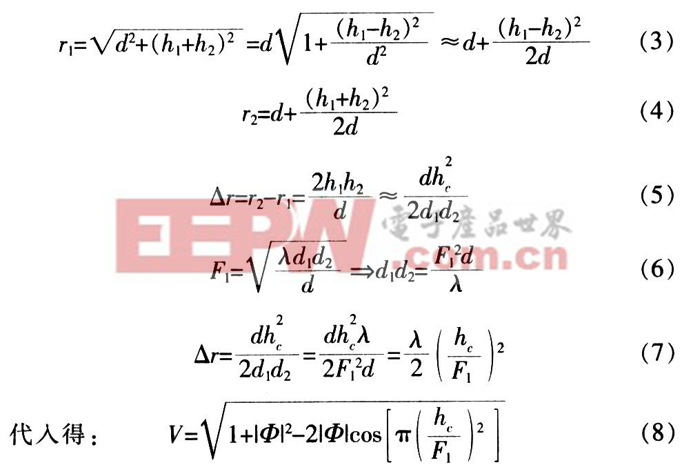
In the formula, r1 is the direct path, m; r2 is the reflection path, m; △r is the travel difference, m; hc is the clearance, m; F1 is the radius of the first Fresnel zone, m; φ is the reflection coefficient.
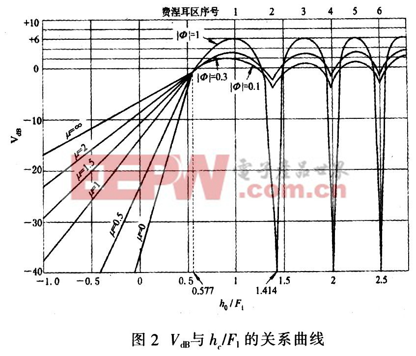
From the above calculation process, it can be known that the fading factor V is related to the relative clearance HC/F1. As shown in Figure 2, when hc/F1=0.577, V=1, VdB=0 dB, and the received field strength E=E0. At this time, the clearance has a special meaning, which is denoted as h0=0.577F1. Free space clearance. When hc/F1<0.577, the diffraction fading is large; as the clearance increases, the reflection point is in the first Fresnel zone, and the reflected signal and the direct signal are added in phase to make the fading factor appear positive; When the clearance increases to a certain extent, the reflection point enters the second Fresnel zone, and the reflected signal is in phase with the direct signal, and the fading factor drops sharply, even causing signal interruption.
2.3 The influence of the atmosphere
Charged particles in the atmosphere have their fixed electromagnetic resonance frequency. When they are close to the resonance frequency, they will produce resonance absorption, causing microwave attenuation, but the attenuation relative to free space is negligible; in addition, small water droplets in rain and fog will also It causes electromagnetic waves to scatter and fade, generally below 10 GHz, and the attenuation is not serious. Therefore, the main study here is the influence of atmospheric refraction.
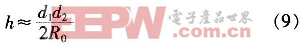
The inhomogeneity of the atmosphere causes the composition, pressure, temperature and humidity of the atmosphere to change with altitude, causing the refractive index of the atmosphere to also change with altitude, which will cause the propagation direction of radio waves to change, and the reflection and direct radiation of the ground will cause microwave multipath fading. . The ratio of the propagation speed c of radio waves in free space to the propagation speed v in the atmosphere, that is, n=c/v. When there is no refraction, the radius of the earth is R0, the clearance is hc, and the height of the earth protrusion is h. d1 and d2 are the horizontal distances from the reflection point to the receiving and transmitting ends respectively. Then the height of the earth protrusion at any point is:
Considering the refraction of radio waves, the equivalent equivalent earth protrusion height of the earth equivalent radius Re is:
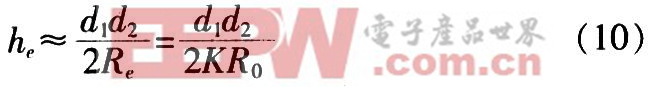
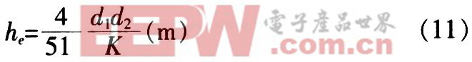
In the formula, d1 and d2 are in km, and R0=6 370 km. Substitute into formula (10), then:
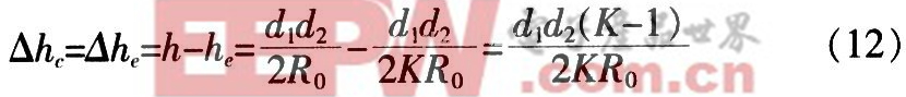
Suppose the change in the height of the bulge of the earth is △he, in terms of value, the change in the clearance is the change in the height of the bulge of the earth. which is:
The equivalent clearance hce is:
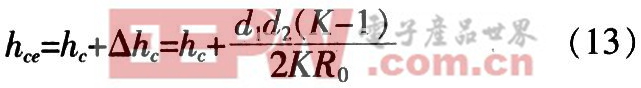
From equation (13), it can be seen that when K>1, when positive refraction, the equivalent clearance hce increases; when K<1, when negative refraction, the equivalent clearance hce decreases. In the actual selection of antennas, various factors should be considered comprehensively, and the impact of terrain, ground reflection and atmospheric refraction should be considered.
3 Research on optimization methods of microwave antennas
In order to ensure that the transmitting end of the microwave antenna can effectively send the signal to the destination or relay station, and the signal can be reliably received at the receiving end, certain optimization measures should be taken on the basis of fully considering the influence of the ground, atmosphere and other natural factors.
3.1 Optimization of diversity technology
Diversity technology is to select or combine the output signals of multiple receivers with less correlation at the receiving end, thereby reducing the impact of multipath fading. Diversity technology is achieved by finding and using independent (at least highly uncorrelated) multipath signals in the natural wireless propagation environment. If one wireless propagation path has experienced deep fading, the other relatively independent path may still contain Strong signal, so you can select 2 or more signals from multiple signals to combine, so that the instantaneous signal-to-noise ratio and average signal-to-noise ratio of the receiving end can be improved at the same time. Generally it can be increased by 20~30 dB. The specific implementation methods are as follows:
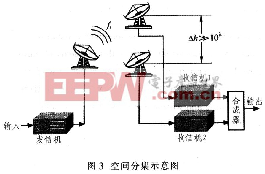
(1) Space diversity is also called antenna diversity. Figure 3 is a form of diversity that is used more in mobile communications. Multiple receiving antennas are used to receive signals and then combine them. In order to ensure the independence of the received signal, the distance between the antennas is required to be large enough. In an ideal situation, the distance between the receiving antennas only needs to be greater than half of the wavelength λ. From a technical point of view, the greater the number of diversity antennas, the better the performance improvement, but when the diversity multiples reach a certain level, the diversity multiples will continue to increase, and the performance improvement will gradually decrease. Therefore, it is more appropriate for the diversity multiplicity to be 2 to 4.
(2) Polarization diversity In a mobile environment, the horizontal and vertical paths in the air are uncorrelated, so the signal also exhibits uncorrelated fading characteristics. Two antennas are installed at the transmitting and receiving ends, one horizontally polarized antenna and one vertically polarized antenna, and two unrelated signals can be obtained. When the number of cellular mobile users increases sharply, this technology is effective in improving link transmission efficiency and increasing capacity.
(3) The angle diversity signal is affected by the environment during the transmission process, so that the signals arriving at the receiving end cannot be in the same direction. In this way, installing a directional antenna at the receiving end can combine unrelated signals.
Diversity improvement effect refers to comparing the effect of using diversity technology and not using diversity technology on reducing the effects of deep fading. The nominal improvement effect is commonly used to quantitatively measure the improvement degree of diversity, which is described by two indicators: diversity gain and diversity improvement. Diversity gain refers to the difference between the reception level of diversity reception and single reception within a certain cumulative time percentage. The greater the level difference, the higher the diversity gain, indicating that the diversity improvement effect is better. Diversity improvement refers to the ratio of the cumulative time percentage of fading between single reception and diversity reception at a certain relative reception level. The larger the ratio, the better the diversity improvement effect.
3.2 Optimization of adaptive equalization technology
When radio waves radiate in space, they are transmitted through multiple paths due to reflections from mountains and buildings. The received signal at the receiving end is the superposition of different delay waveforms of each path. Bandwidth limitation and nonlinearity will cause signal waveform distortion and cause crosstalk between adjacent symbols. All of the above situations will cause bit errors. Adaptive equalization is to use the equalizer at the receiving end to produce characteristics opposite to the channel characteristics to offset the interference caused by the channel time-varying multipath propagation, which can eliminate waveform superposition and inter-symbol crosstalk, and can also reduce additive noise interference, thereby reducing errors Code technology. Equalization is divided into frequency domain equalization and time domain equalization. Frequency domain equalization means that the total transmission function satisfies the condition of distortion-free transmission. Time domain equalization is to make the total impulse response meet the conditions of inter-interference. In actual circuits, frequency domain and time domain adaptive equalizers are often used at the same time to maximize the circuit's anti-fading ability.
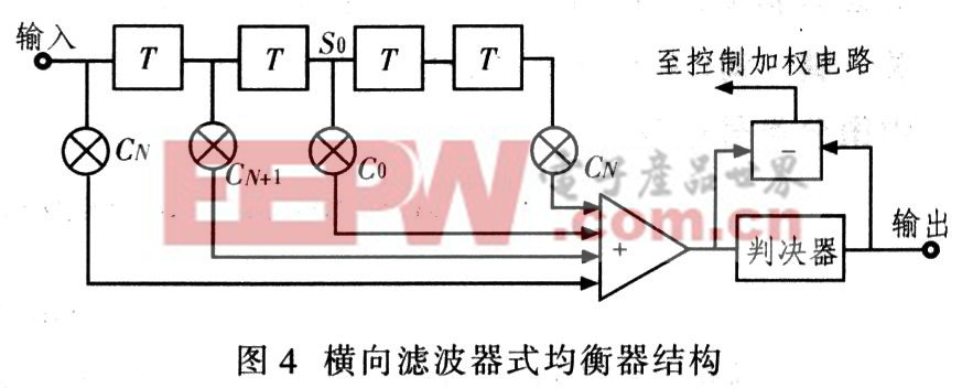
Figure 4 is a schematic block diagram of the most widely used horizontal filter equalizer. The horizontal filter of this equalizer is composed of a 2N-stage delay line T and an adjustable weighting circuit, each with a delay of 1 bit. There are N pulses before and after the middle (center tap) pulse S0, and there are 2N+1 pulses in total.
3.3 Optimization of impedance matching
The input impedance of the antenna is the ratio of the input voltage to the input current at the antenna feed end. For the connection between the antenna and the feeder, the best case is that the antenna input impedance is pure resistance and equal to the characteristic impedance of the feeder. At this time, there is no power reflection at the feeder terminal, no standing wave on the feeder, and the antenna's input impedance changes smoothly with frequency. The impedance matching of the antenna is to eliminate the reactance component in the antenna input impedance and make the resistance component as close as possible to the characteristic impedance of the feeder.
4 Conclusion
Microwave antenna is an indispensable part of wireless communication, and its performance directly affects the indicators of the communication system. Characteristic parameters describing microwave antennas include pattern, directivity, gain, input impedance, radiation efficiency, polarization, and bandwidth. Discuss the factors that need to be considered when selecting microwave antennas, and propose optimization schemes from the aspects of diversity technology, adaptive equalization technology, impedance transformation, etc., with certain innovative ideas.

点击右上角
分享给朋友吧


 Long by picture save/share
0
Copyright © Xiamen Lineyi Electronics Co., Ltd All rights reserved.
点击右上角
分享给朋友吧
